CD player progress
I've kept working on the CD player that I mentioned last time! I've finally got something physical to show for it. I've been doing a bunch of soldering to get stuff wired up. I used to be pretty bad at soldering, but through all the soldering I've been doing recently I've gotten pretty comfortable with it now.
In case you missed the last post, here's the model I have for the CD player so far:
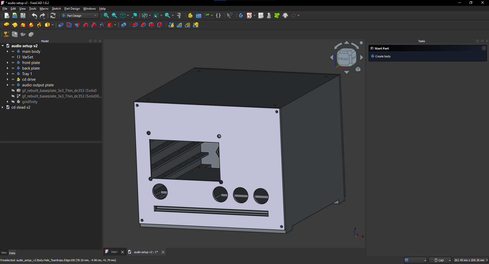
I'll show off the parts I've made so far one by one, and give a little explanation about some of the decisions I made.
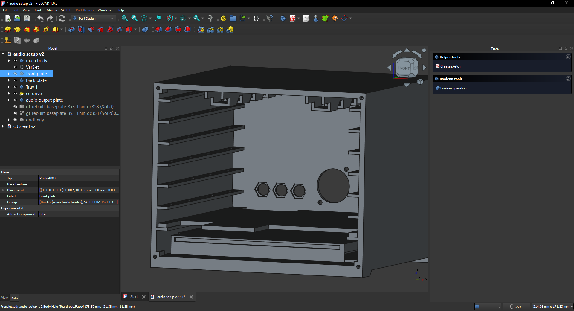
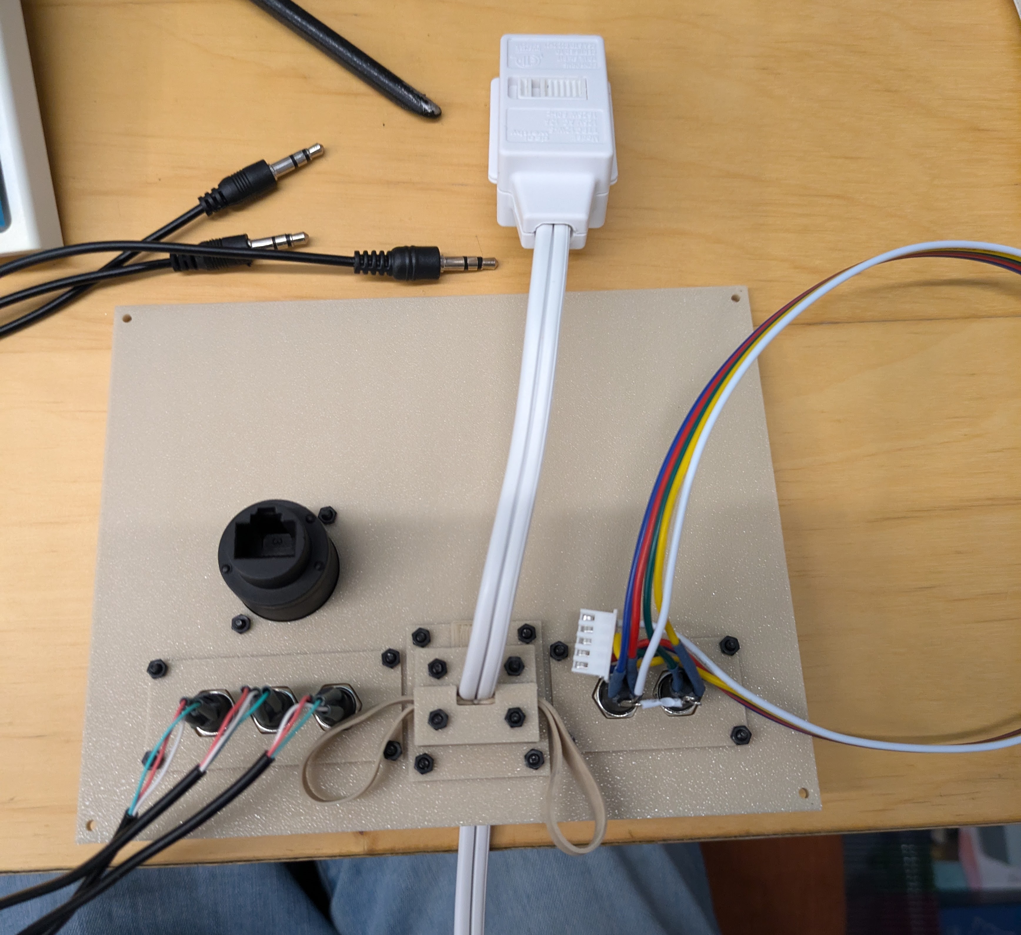
So first, here's the front plate:
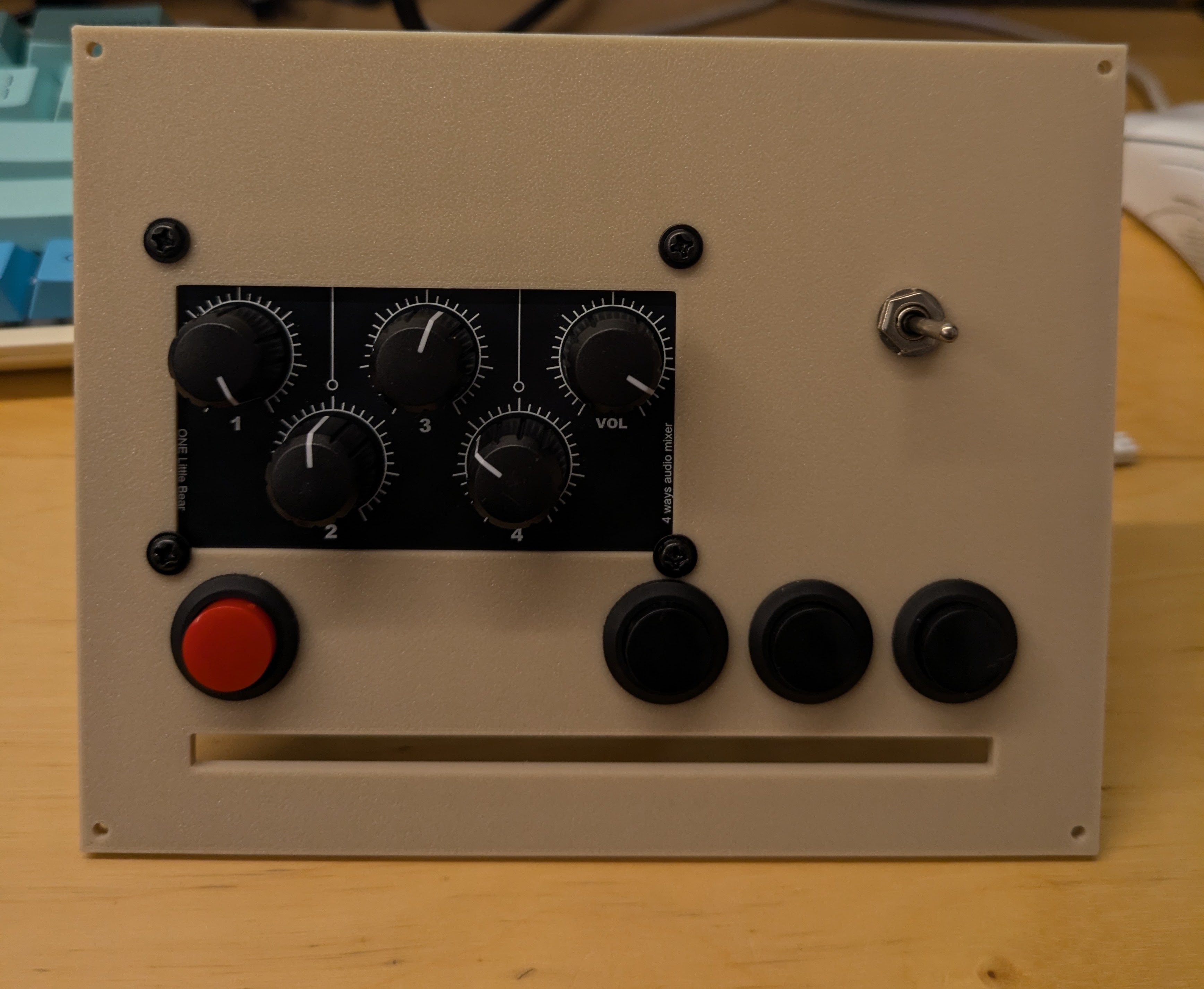
The buttons are for pause/play, skip track, previous track, and eject disk. The knobs are part of a mixer. It's for adjusting the volume of whatever audio devices I plug into the player as well as the cd volume output. The switch is for switching the output device, that way I can switch between my speakers and headphones really easily. I learned from someone on youtube that you can purchase a guitar switch and repurpose it as an audio output switcher. Which is great, because an audio output switcher is large, usually has no clear way to mount it in something, and costs at least $17. But I was able to get a pack of 5 guitar switches for $3, plus it allowed me to use less 3.5mm cables which saves some more money on its own too.
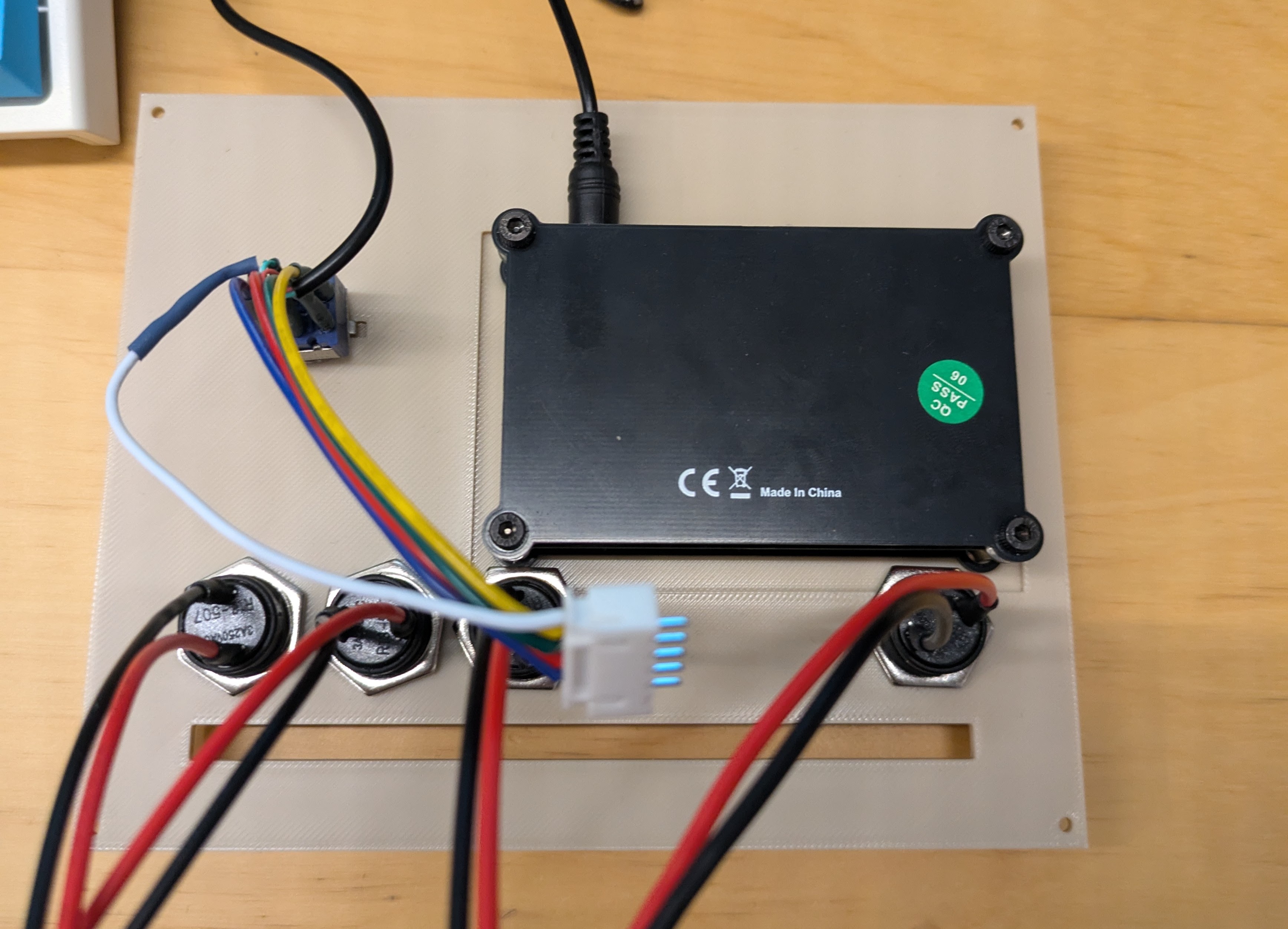
Now here's the back plate:
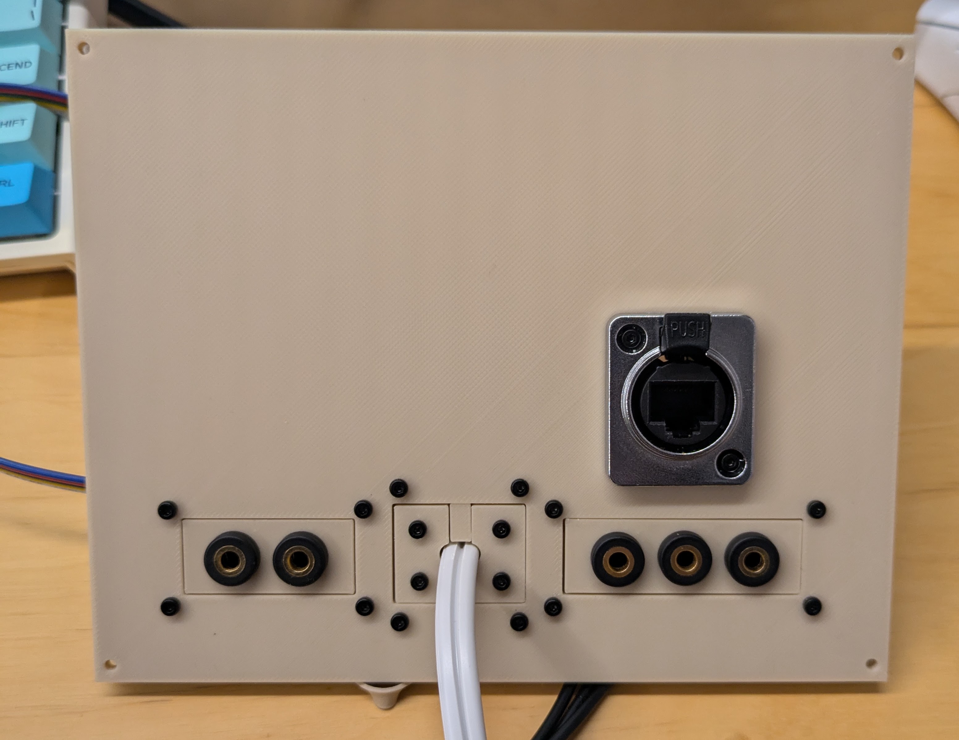
So I have 3 inputs that go into the mixer out the back, and the two outputs which can be switched between! I also have an ethernet port so I can get a connection to the raspberry pi inside (it doesn't have wifi). The whole thing will be powered by that power strip. I've secured it in place with a clamping mechanism, so it won't slide in or out easily.
Annd finally here's the first shelf:
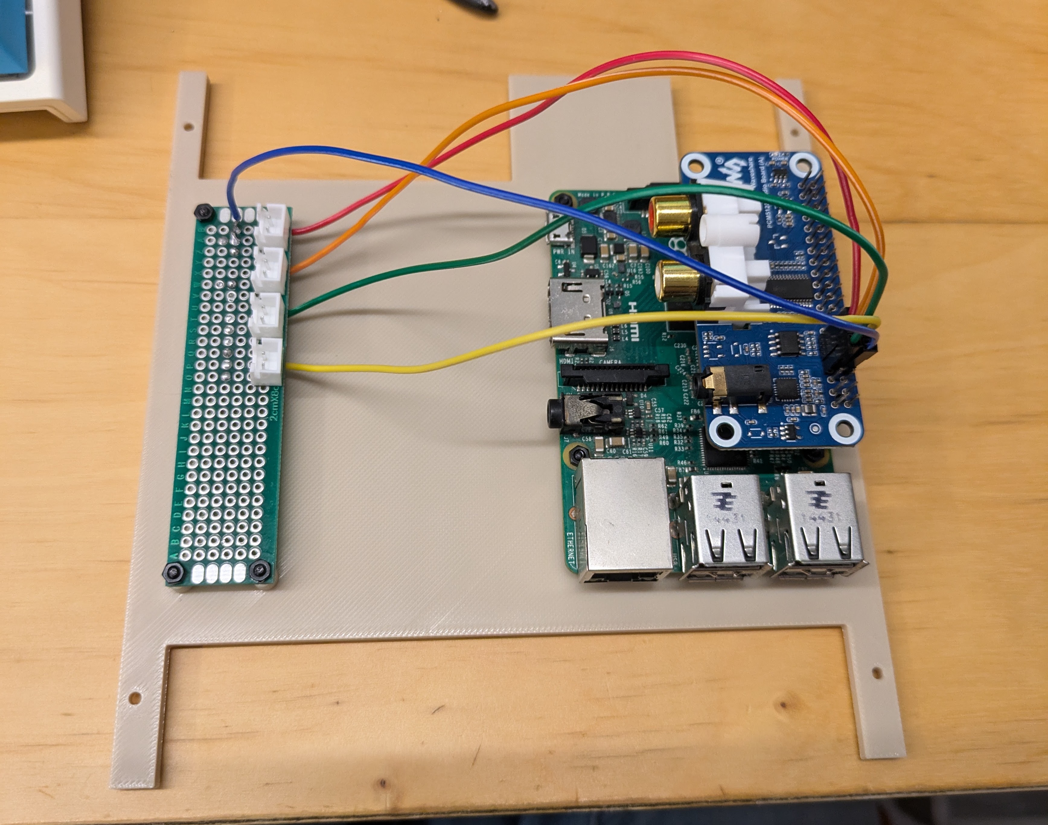
It's designed just to hold the Raspberry pi and the little circuit board that the buttons attach to. There's some empty space I'd like to utilize, but I don't think I can. All the other components I need to fit inside are too big for this shelf :'(. The power strip and the adapter for attaching the CD player to the raspberry pi wil need to fit on another shelf, which I'm yet to design. I think I'm going to need to redo this one though. The optical drive is going to attach to the raspberry pi via usb, and the usb ports are pointing right at the back plate. I don't think it leaves enough room for the connector. Oh well, there's bound to be some waste I suppose whenever you make projects.
The only thing that isn't really going fairly smoothly about the project so far is powering the optical drive. It's a sata laptop optical drive, so I need an adapter to connect it to the raspberry pi over usb. The usb port doesn't provide enough power to drive an optical drive, so I bought a powered adapter. However, it turns out the powered adapter only provides power to the 12v wires over the sata power connector and uses the usb port for it's 5v power. The problem is a laptop drive uses a "slimline" connector, which only carries 5v power. So the 12v power being provided is meaningless and the cd drive can't work properly because it's not receiving enough 5v power.
So I need to find some other way to power it. And you know what provides 5v of power and I have a lot of? Phone chargers! So my new plan is to connect the output of a phone charger right to the power input of the cd drive. I tried connecting the leads of a usb-c cable right to the power input leads, but unfortunately that didn't work. I did some research and found out I need to put resistors on certain lines to get more than 500ma out of my phone charger. So I ordered the relevant parts! Hopefully no magic smokeage occurs :p. Wish me luck. Or uh email me to warn me if you know something I don't and know I'm about to fry my optical drive haha
Off to bed, I'll update you all when I get the main body printed and assembled :)