Using photos in Freecad
If you're a regular Freecad user, I'm sure you're familiar with the difficulty sometimes posed when attempting to model complex curves or shapes made to fit a real world object. If you are, then this short little tutorial is for you. You will learn how to take a good photo, correct the off angle distortion, and size the image correctly.
The problem
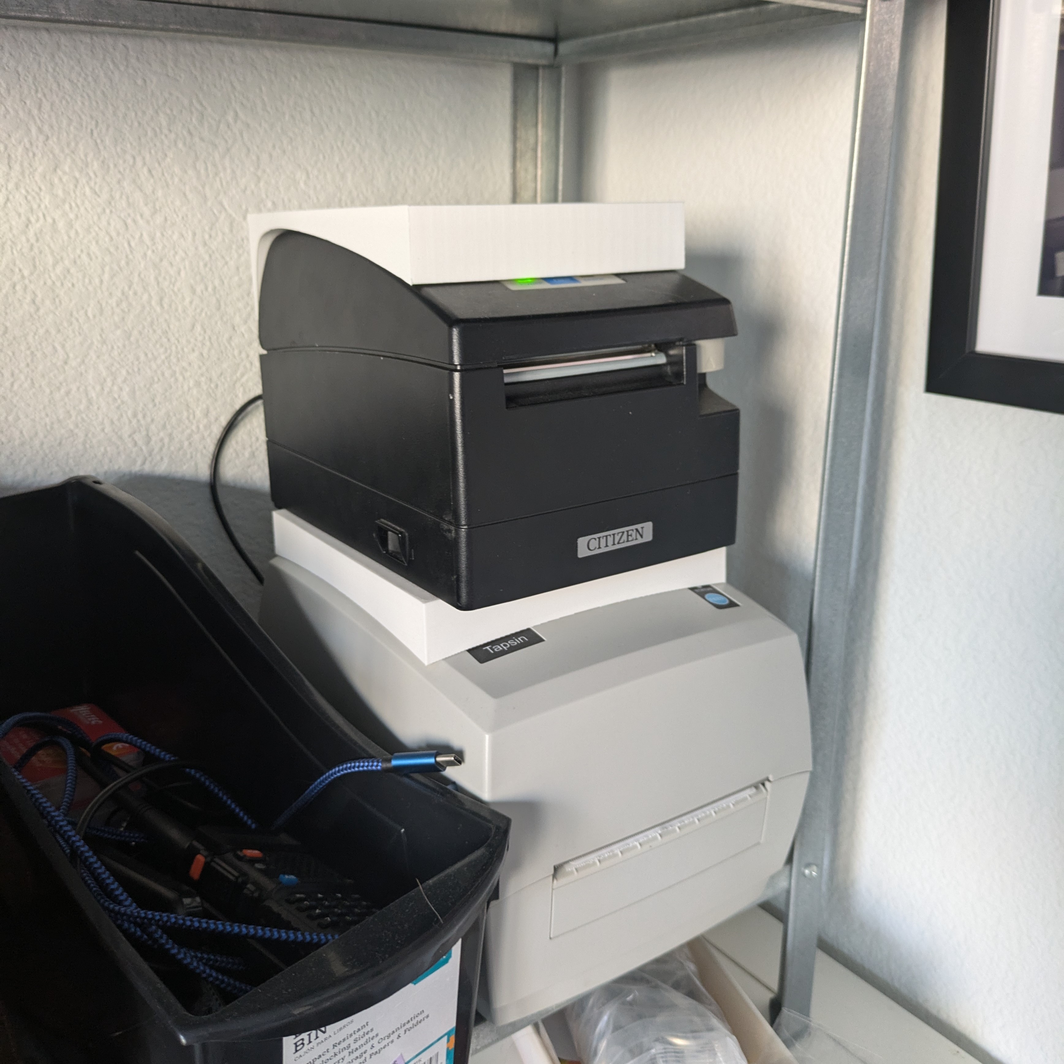
As part of my home setup for my etsy store, I have a receipt printer. The printer works great, however the footprint of my receipt printer is much larger than I would like. This wouldn't be that much of a problem, but annoyingly the top surface is curved which renders all space above it unusable. I'm always starved for space in my apartment and every inch of shelf space really does make a difference to me.
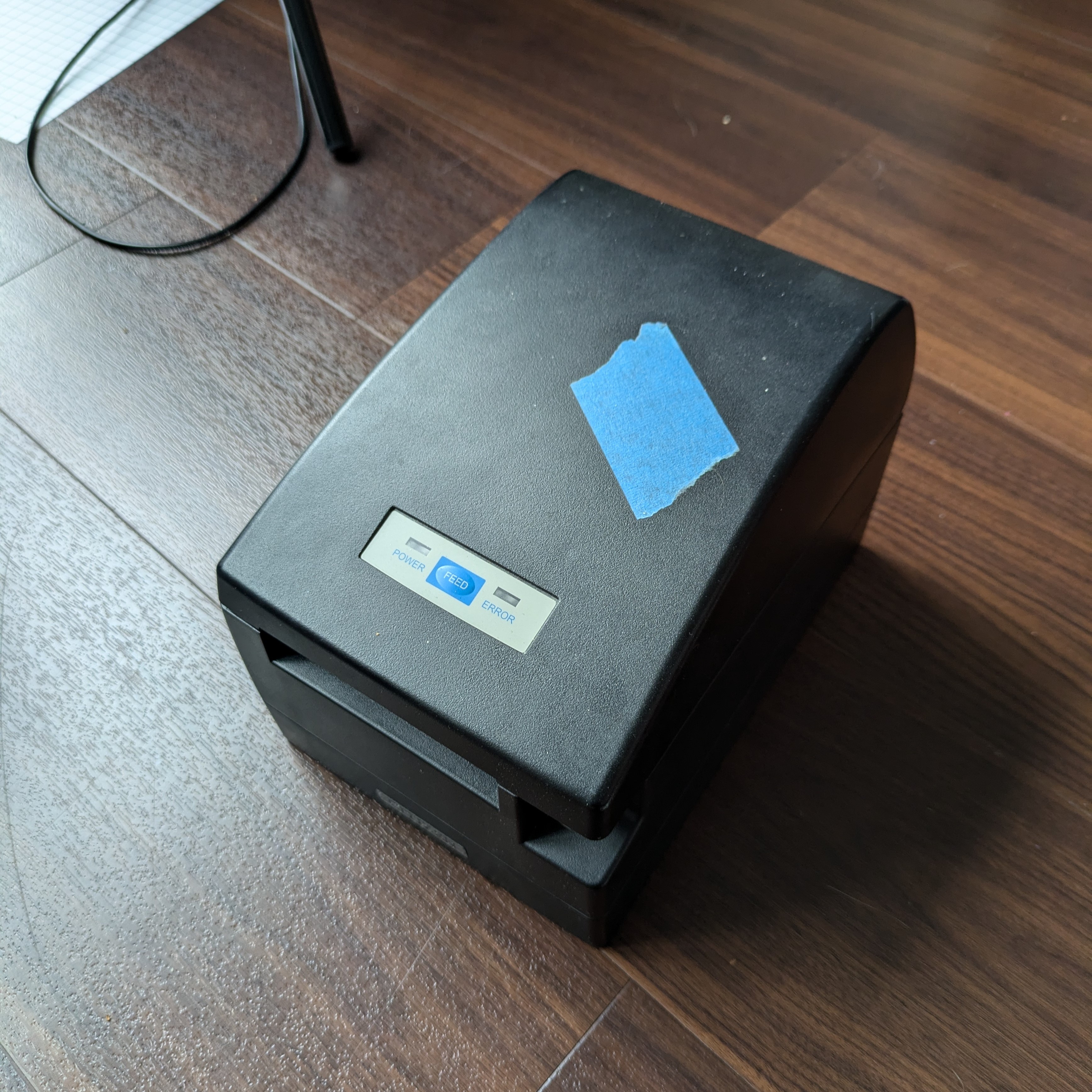
I wish it just had a flat top!
I'd like to make the top of the receipt printer flat by 3d printing a custom part, but to do that I'll need to accurately model the curve on top of the printer. Though I've tried, using a caliper to measure the curve is both difficult, and you cannot be certain your results are accurate.
The tools
To retrace my steps properly with your own object, you'll need the following tools:
-
A camera
- A phone camera will probably be okay, although a camera with a nice lens will net better results as there will be less distortion
- Freecad (1.0 used in this tutorial)
- Darktable (4.8.1 used in this tutorial)
This tutorial isn't for complete beginners to Freecad. If you don't know the very basics yet, it may be difficult to follow along. If you're new to Darktable, no worries! That part won't be too bad.
If you'd like to follow along with my exact images, you can get the source image I used here:
Project files
Taking the picture
If you have a camera, it will be most ideal to use a longer focal length prime lens for minimal distortion. In my case, I'm using an Olympus 45mm f1.8 lens. If you only have a phone camera, I'm sure it will turn out just fine too. If your phone camera has a "2x" mode, use that. Make sure to stay away from the ".6x" mode or similar as there will be increased distortion from the wider angle lens.
In our photo editing step, we're going to need vertical and horizontal lines that are known to be level to properly correct for the perspective distortion and rotation. If you're lucky, the object you're taking a picture of may already have such lines. In this case however, I'll need to add my own to the photo.
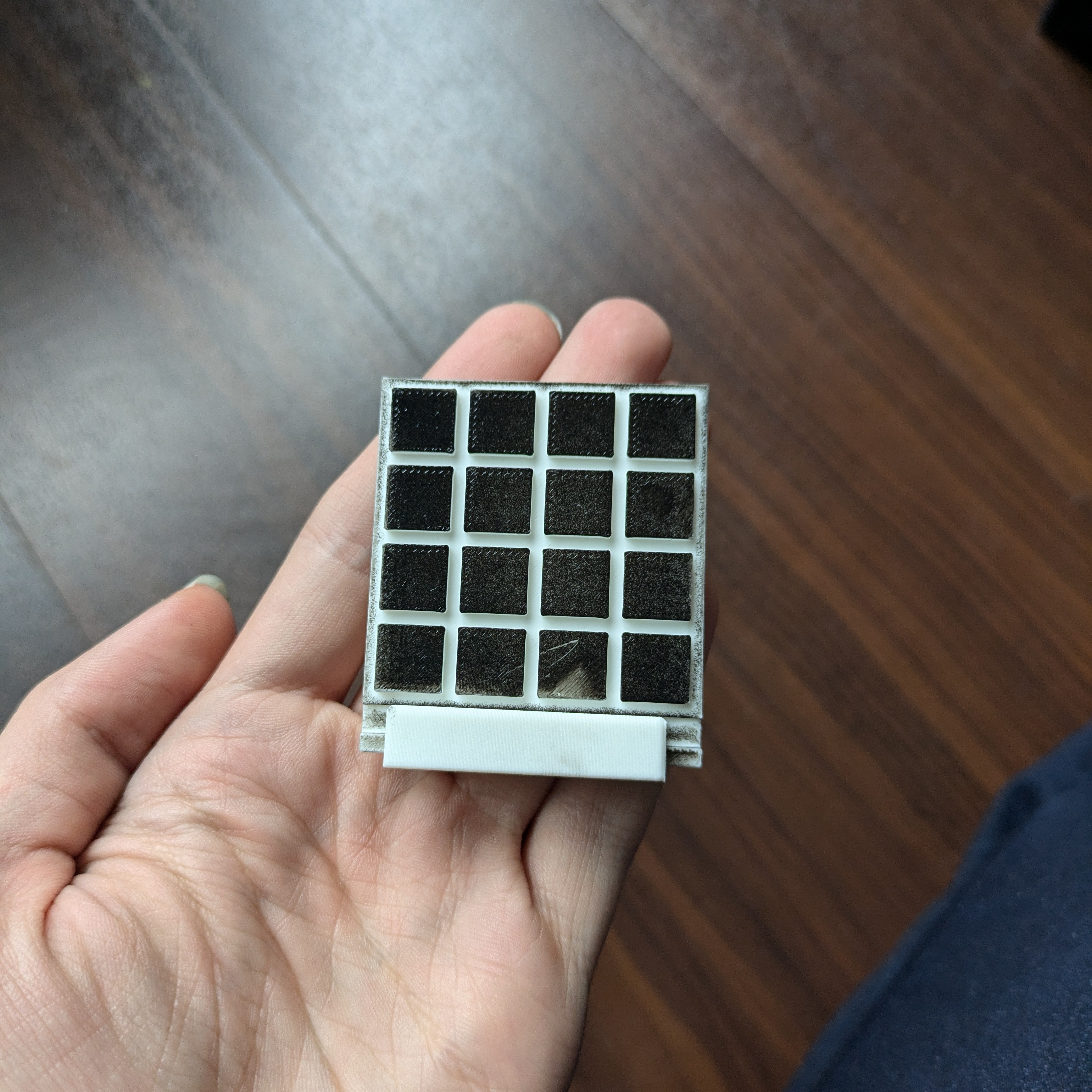
I've printed this grid and stamped it against an ink pad to give the raised parts of the grid extra contrast. You could use any other object with precise level lines too. Make sure the helper object is very exactly aligned with the plane of the object you are photographing. Additionally, be sure you have an object you know the exact length of in view. This could be a ruler or similar. In my case I happen to know the exact length of my grid object from the leftmost square to the right is 49.9mm.
If you'd like to use my grid design, you can download the source and stl's here:
Grid source and stl's
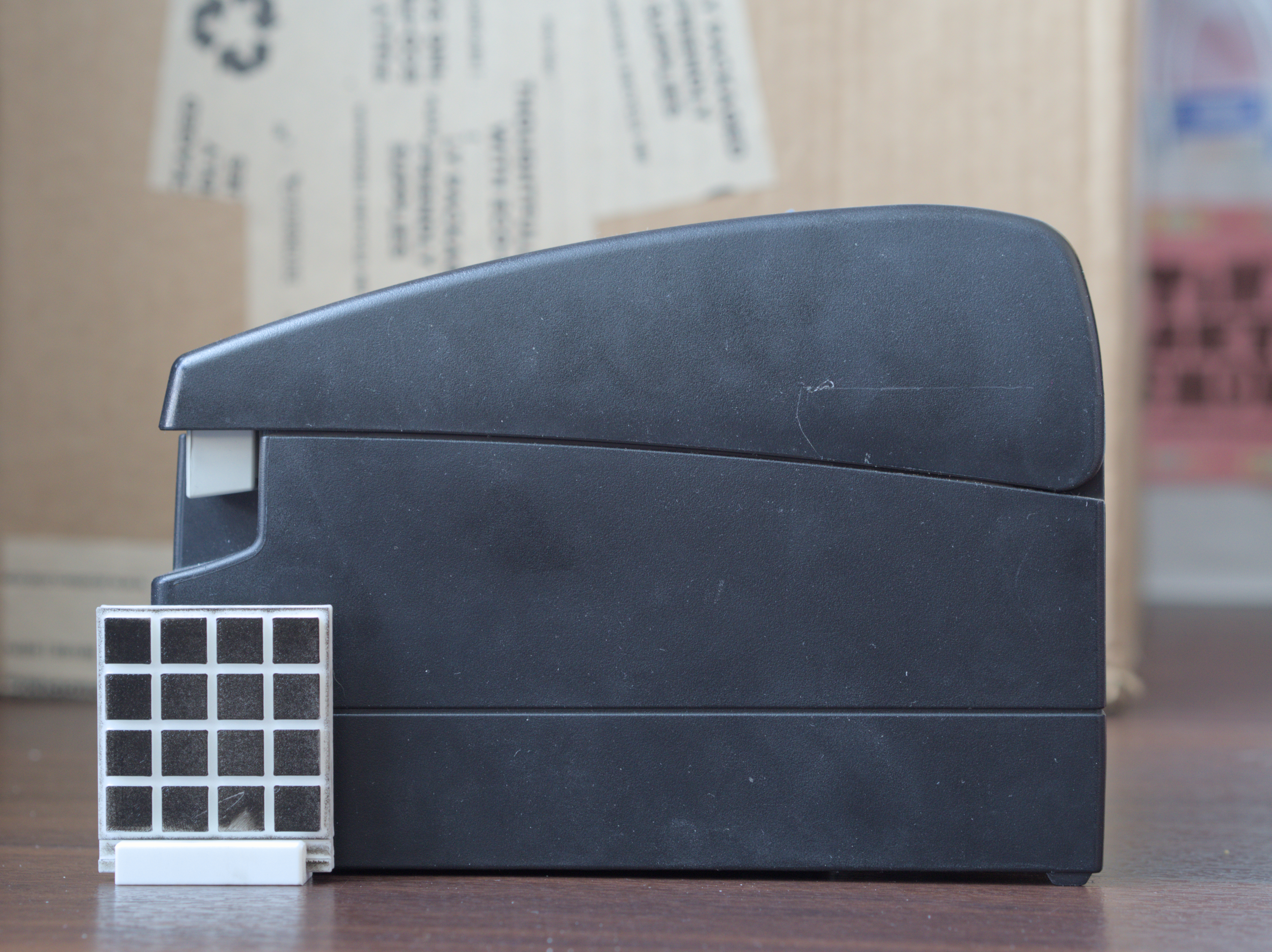
Now, just hold your camera to be as level and straight on as possible with the face of the object, make sure you have a contrasty background, and shoot the photo. Take a few pictures in case one turns out better than another.
Editing the photo
Let's move on to correcting the photo's perspective distortion in Darktable. No matter how level and straight on you shot your picture at, I can almost guarantee you it wasn't perfect.
First, we should import your photos into dark table. Create a new directory and copy the photos you took into it. Now, open Darktable. Drag and drop the directory with your images that you created into the application. The center should populate with the images you took. This is called the "lighttable view".
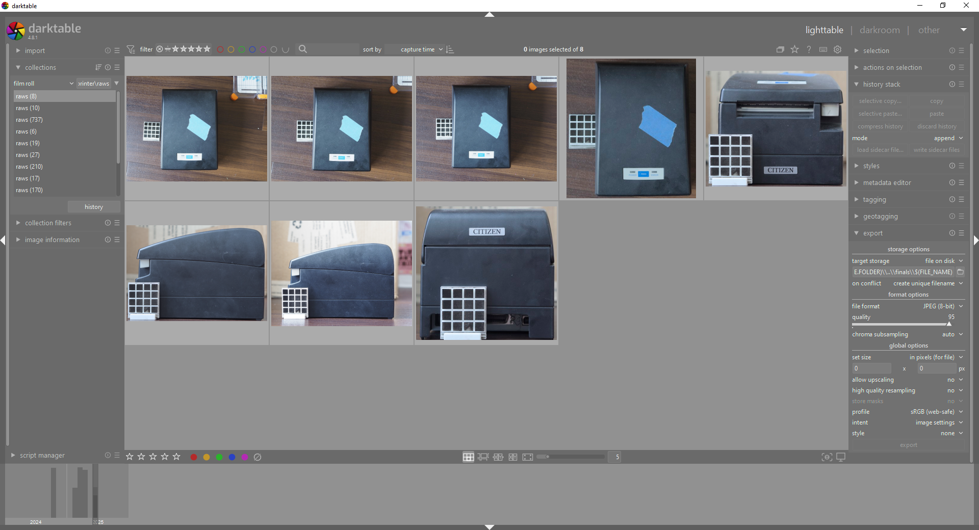
Review the images to decide which one seems best. You can click on a listed image and press f to see a full screen preview of it, then use your scroll wheel to flip between them. Press f again to exit the fullscreen view.
Once you have your best one picked out, double click it. This will take you to the "darkroom view" where you do all of your editing.
If you're using a phone camera, skip past this step.
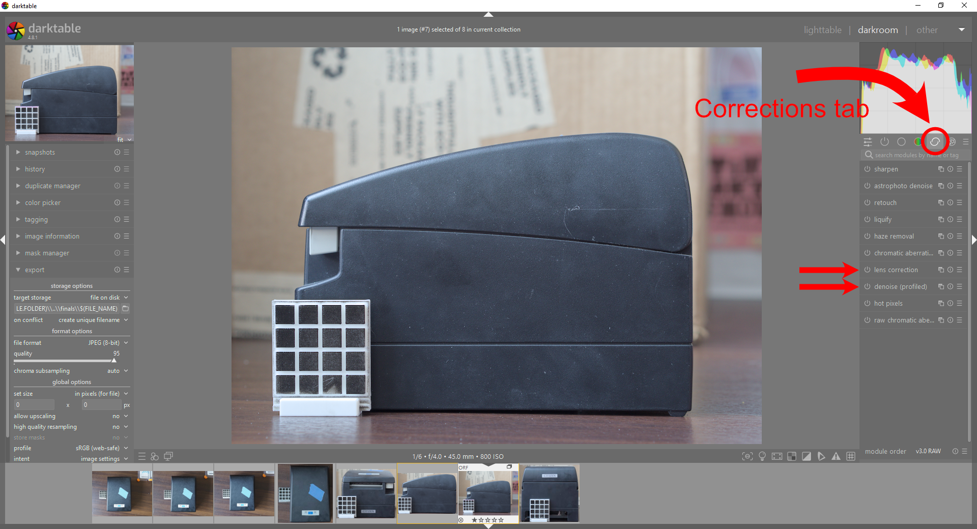
If you have a supported electric camera lens, we can apply a lens correction to correct for any lens distortions. Navigate to the "corrections" tab pointed out in the image above and enable "lens correction". It uses information from a database to correct for your specific lens' distortion
We can also remove some of the noise from the image. Just enable "denoise (profiled)". This will use information from a database of camera bodies to apply denoising specific to your camera body and iso.
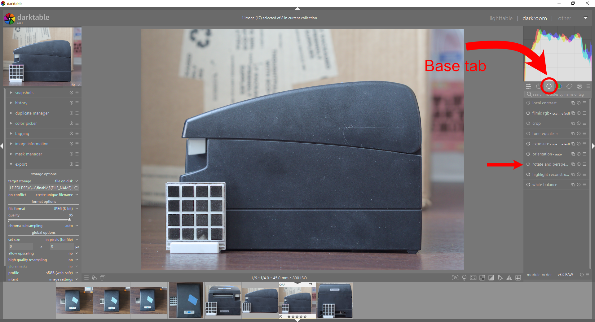
Select the "base" tab as pointed out in the image above. Click on "rotate and perspective" to expand the options. This is where we'll correct for the off angle distortion.
Under the "perspective" section select the pencil tool. You can draw a line by clicking, dragging, then releasing. You can edit a point after by dragging it. You can delete lines by using right click. Use this to accurately trace the horizontal and vertical lines in the image. Between 3 and 6 both horizontal and vertical lines is ideal.
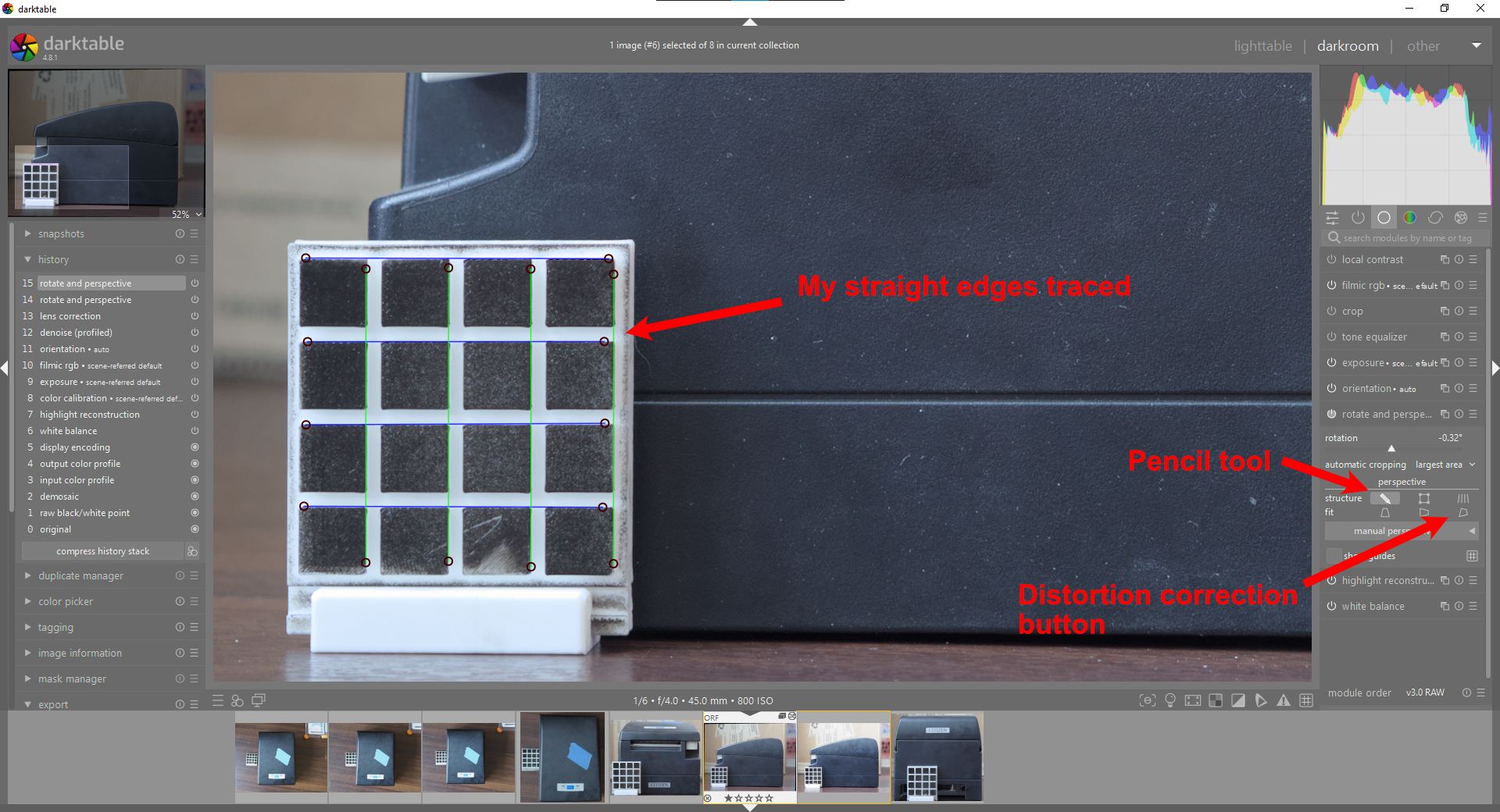
Now click the distortion correction button as pointed out in the image above. This will slightly shift the perspective of the image to minimize the perspective distortion! It will also adjust the rotation to be level.
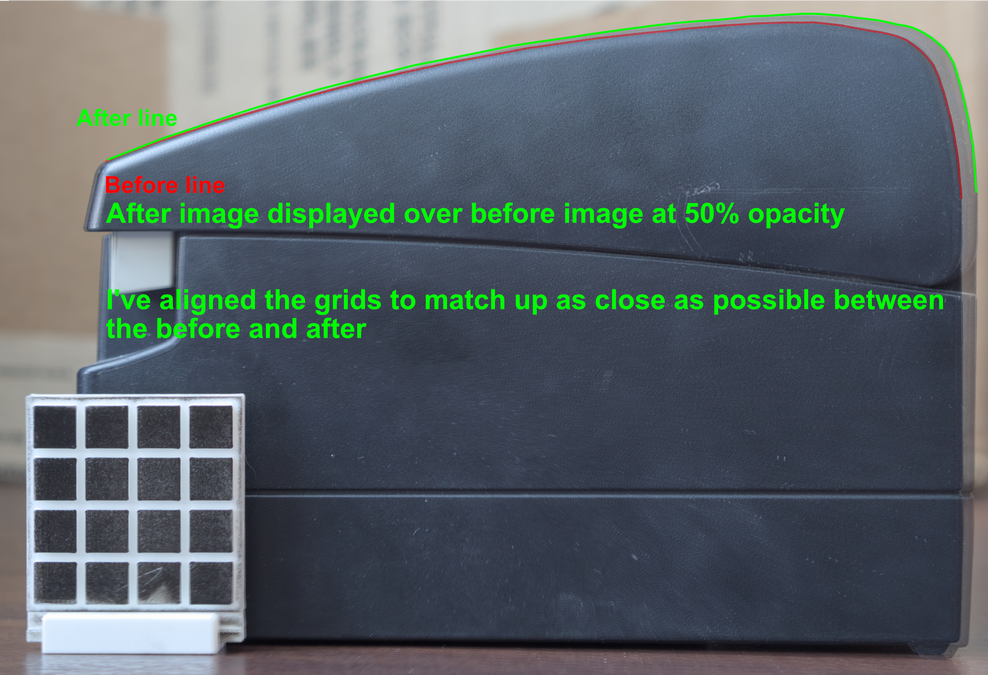
The difference may be slight. In my case, even though the difference is visually slight, the edge I'm going to trace has a noticeably different shape between them. This is why the extra work of correcting for the distortion and rotation is worth it! If you would like, you may crop the image using the "crop" module, located a few modules above the "rotate and perspective" module.
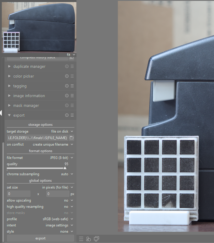
Now all that's left to do is to export the image! On the left sidebar, open the "export" menu. Under "target storage" select "file on disk". Then, use the folder icon to select where you would like the image to be saved to.
If you know what you're doing, go ahead and fill out the rest however you want and export. Otherwise, feel free to copy my export settings.
Now that you have the image exported, we're all done with darktable! Now lets move into Freecad.
Importing the image into Freecad and sizing it.
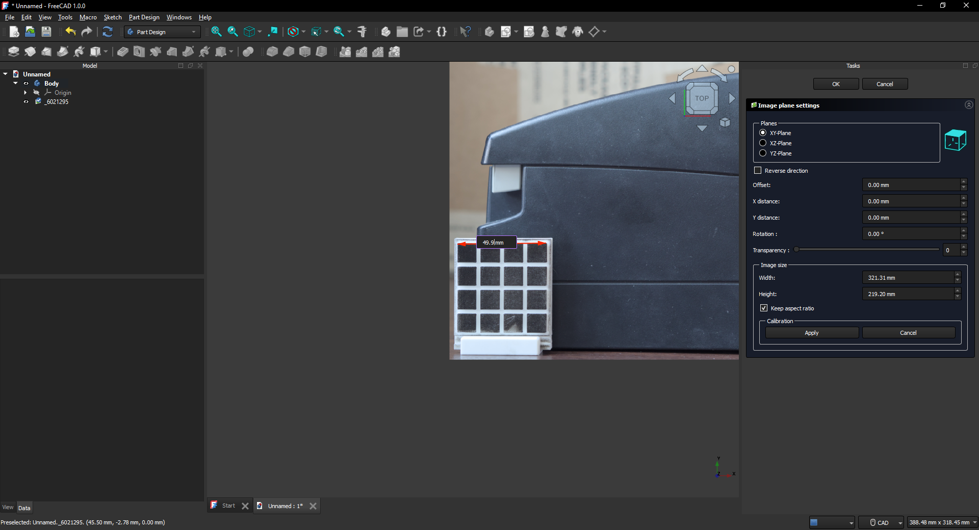
This part is pretty easy. Open Freecad create a new "parametric part" file. To import the image all you need to do is drag and drop the image into the 3d view in Freecad. Now that we have the image, we'll want to size it to scale.
Make sure you view the image straight on for this part. You can click on the faces of the cube in the upper right to adjust your view precisely
The image should display on the node menu. Double-click on the image to edit its settings. Click the "calibrate" button. Use your mouse to precisely click on two points in the image you know the distance of, then in the text box write in the distance between those points and press enter. Viola, your image is now sized to scale!
Modeling
This is the part where I sort of toss you in on your own. Your image is imported, just create a sketch and trace whatever your heart desires! However, for completeness’s sake I'll show my process for my specific situation and how it turned out.
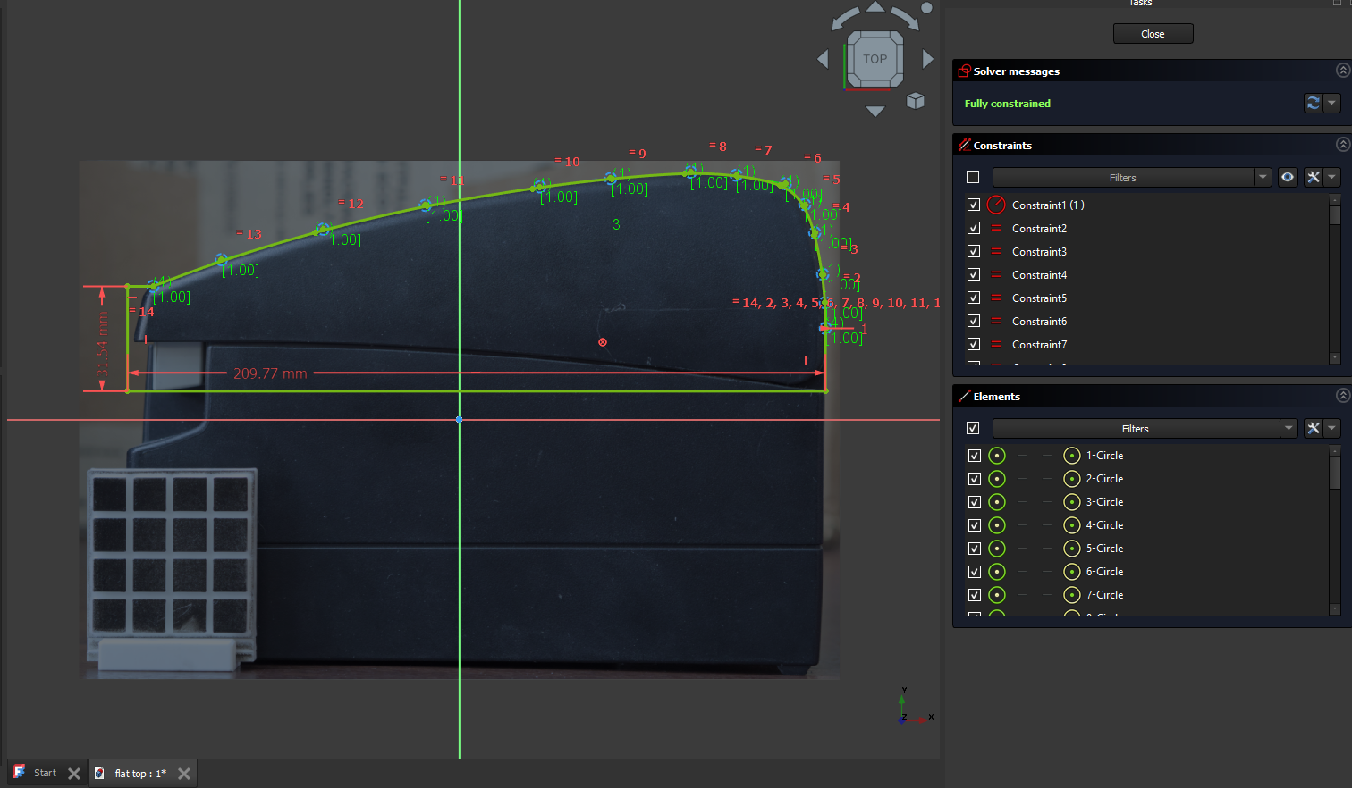
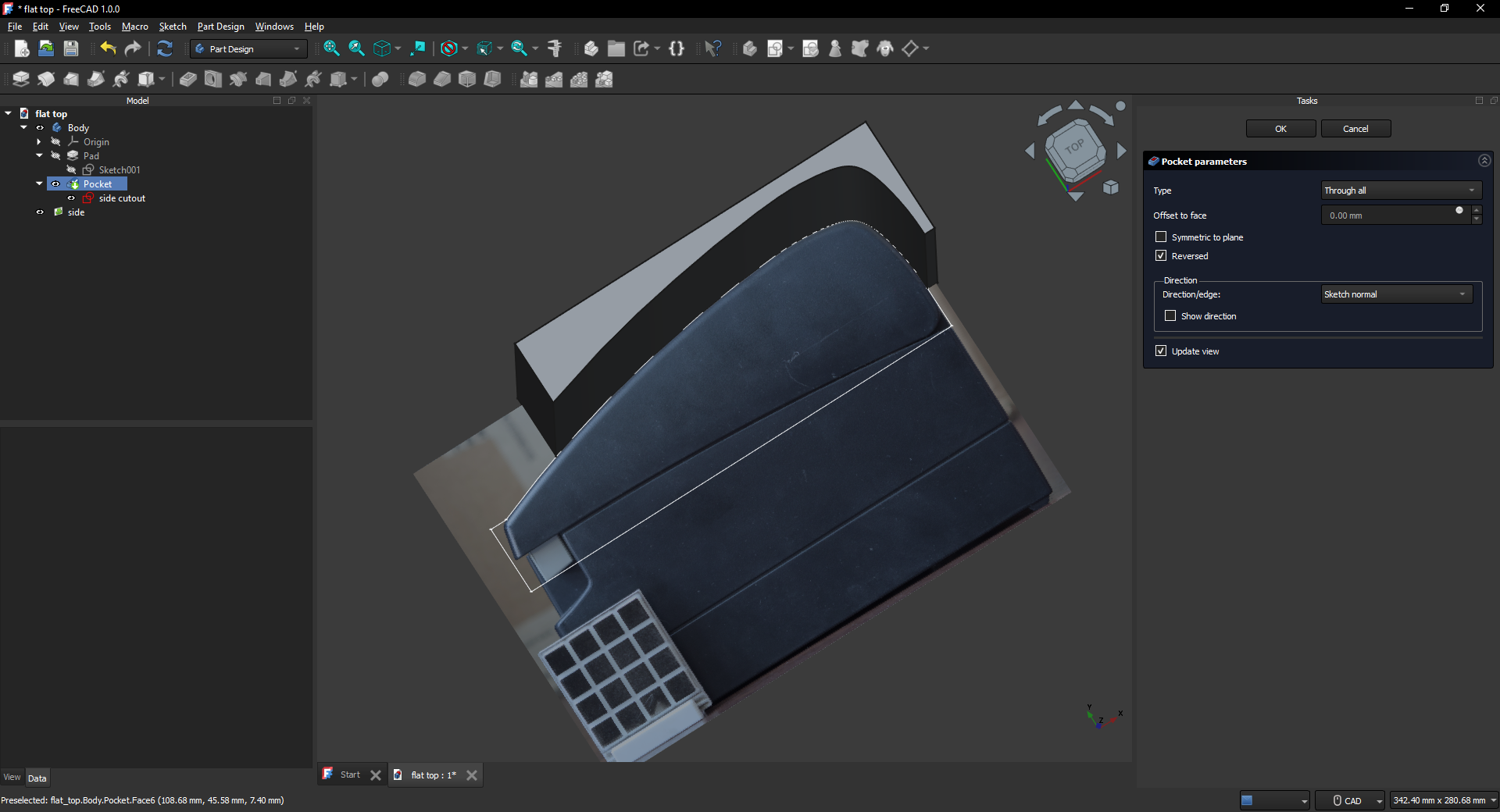
I'm going to create a new sketch on the same plane as the image, then use bsplines to trace the curve. Getting bsplines right can be tricky. My technique is to place a lot of rough points on the curve, then zoom in and align them correctly. Usually you'll need to go through 2 or 3 iterations of alignment as moving 1 bspline affects its neighbours too. Just ignore the affect on the neighbours and go right to left adjusting the points over and over until the curve is perfect to the image.
I don't want to accidentally move any of these points and lose my hard work, so I'll apply anchor constraints to the bsplines to prevent them from moving. Then I'll use a line to connect the two ends so that our wire is closed.
Now I'll create a second sketch, this will be our platform. I'll draw a simple rectangle and apply padding to it.
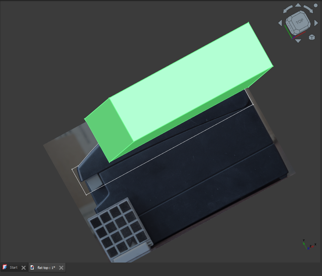
Now I'll use a pocket operation on the first sketch to cut out the shape of the receipt printer. We're left with the completed part!
I've printed it, and it came out as a perfect fit first try. Just a little bit of space has been reclaimed.
My leaning tower of thermal printers can finally grow taller!
I hope this helped you learn something new. If you find yourself stuck or with questions, feel free to email me at mail@crownanabread.com, and I'll be happy to take a crack at it. No promises though, I am still a bit of a novice!